Custom Hardspace Controller pt 2: 20x4 LCD implementation
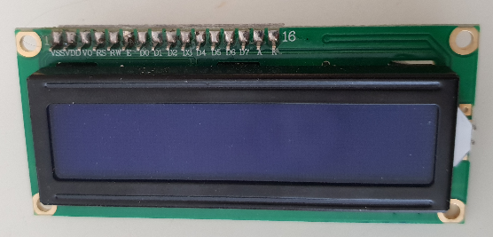
20x4 LCDs are pretty ubiquitous and cheap these days, costing only a few dollars on Aliexpress and so forth. They usually come with the option of a PCF8574 I2C I/O expander board, which can be soldered on quite easily:
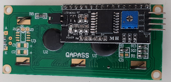
I2C has the advantage of allowing multiple devices to share only a small number of I/O pins, compared with the 8-10 pins that an LCD normally uses, so it was an easy decision to decide to use the I/O expander boards on this project. That means that the actual wiring for these displays is very simple, especially compared to some of the other parts of this project, and only consists of voltage, ground, clock and data wires.
With the wiring sorted, I needed an enclosure for each screen, preferably one that angled it up a little as the viewing angle on these displays is traditionally poor. I've done a lot of work in the past with Rhino3D and Grasshopper, which is a CAD modelling tool that supports node-based systems for generating geometry procedurally. I've got a very big node network that can create arbitrarily sized interlocking enclosures, and optionally angled lids for them:
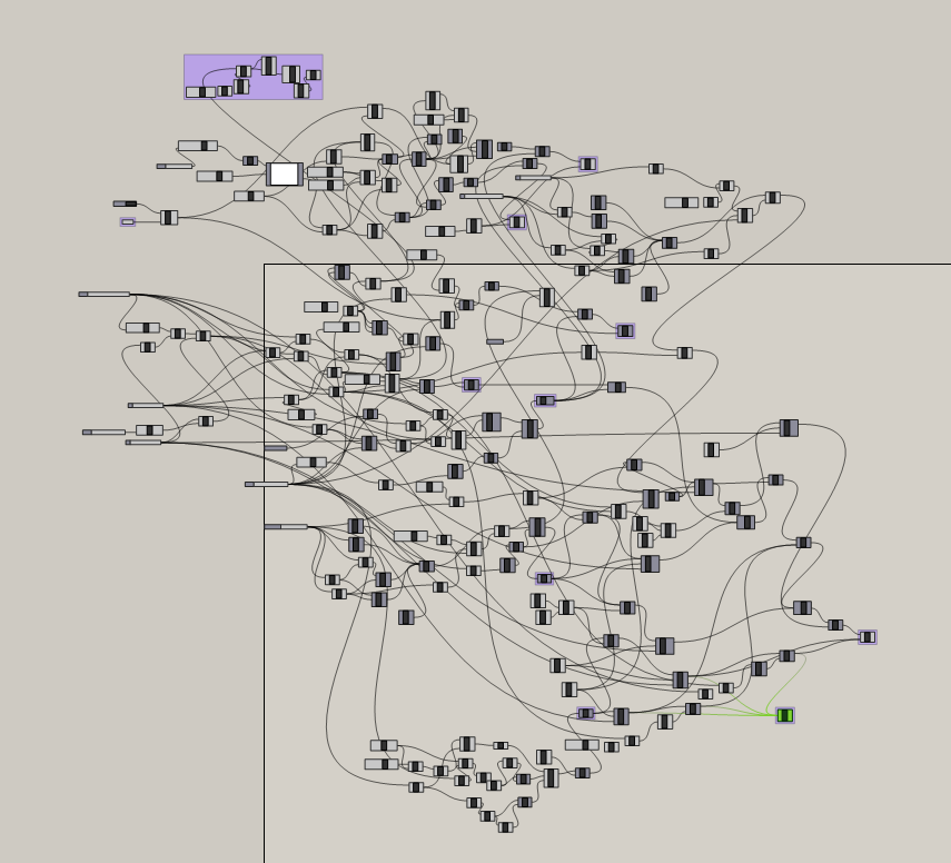
This node network would be even more messy if I didnt add in support for named variable nodes. Seriously.
The generated geometry is easy to slice and 3d print:
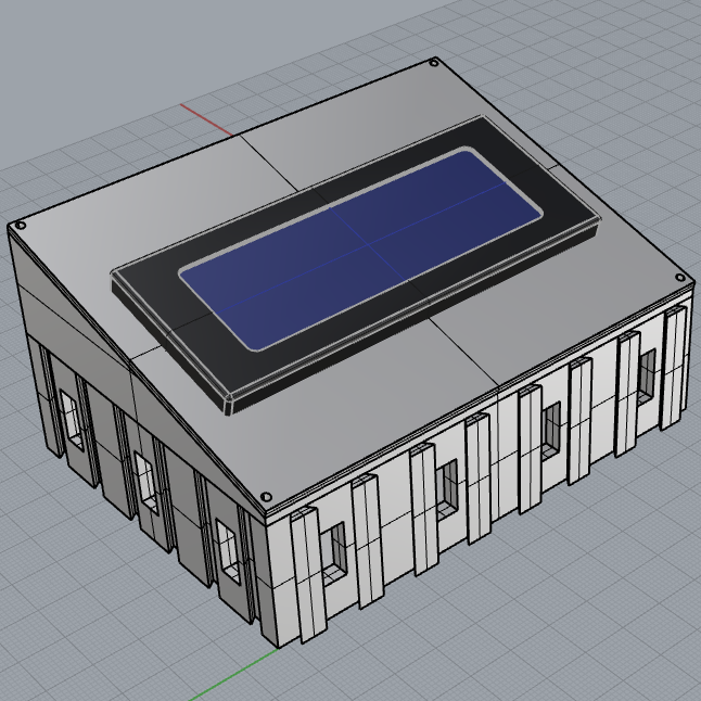
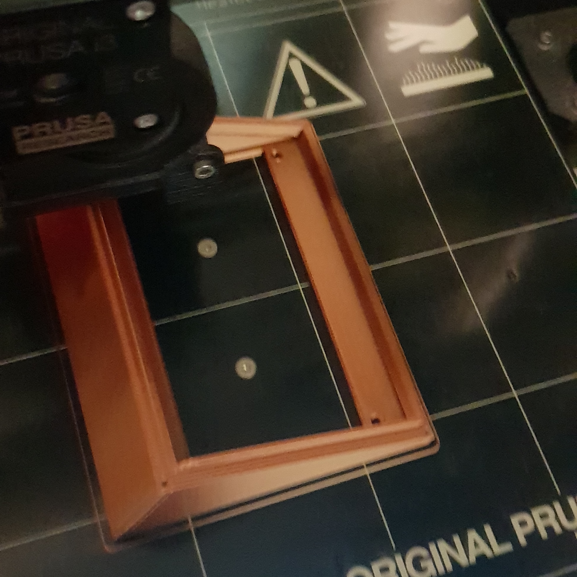
With the enclosure printed, the wiring soldered on, and the LCD itself bolted into the enclosure, I needed to implement the peripheral driver for it.
I already had a driver for the STM I2C peripheral written, so the LCD driver primarily involved defining constants for the commands the LCD required and writing an abstraction for each one and its parameters.
This involved a little effort, because the I2C adaptor requires the use of the LCD's 4-bit interface rather than the 8-bit that might be expected.
The HD44780 LCD uses the following pins:
| Signal Name | Number of Pins | I/O Direction | Function |
|---|---|---|---|
| RS | 1 | Input | Selects destination register 0 : Command register selected 1 : Data register selected |
| RW | 1 | Input | Selects read or write mode 0 : Write mode selected 1 : Read mode selected |
| E | 1 | Input | Data input latch |
| DB4 to DB7 | 4 | Input/Output | High-nibble bidirectional data bus pins |
| DB0 to DB3 | 4 | Input/Output | Low-nibble bidirectional data bus pins. Not used in 4-bit mode |
The I2C expander only has a total of 8 I/O pins, and so there's not enough of those to control RS/RW/E plus all 8 data pins. As a result, the 8 I/O pins are mapped to RS/RW/E, plus the analog backlight control pin, and just the four high-order data pins, this means that we must use the 4-bit mode of the display. This results in the following mapping:
| Device | Pin 0 | Pin 1 | Pin 2 | Pin 3 | Pin 4 | Pin 5 | Pin 6 | Pin 7 |
|---|---|---|---|---|---|---|---|---|
| PCF8574 (I2C adapter) | IO0 | IO1 | IO2 | IO3 | IO4 | IO5 | IO6 | IO7 |
| HD44780 (Display) | RS | RW | E | Backlight | DB4 | DB5 | DB6 | DB7 |
In addition to this restriction, the display has some very specific timing requirements, especially during initialization, to ensure that it is placed into the correct initial state, and requires that the data latch pin be toggled (and held in each state for a certain amount of time) for each nibble of data sent.
This leads to some odd-looking data transmission and initialization code:
static void Send(uint8_t Data)
{
    // Need to toggle the data latch pin along with each nibble of data
    I2C<I2C1>::Write(Address, ClearLatch(Data));

    I2C<I2C1>::Write(Address, SetLatch(Data));
}

static void Initialize()
{
    // Special initialization sequence is a series of high-nibble-only writes which force 4-bit mode regardless
    // of initial state

    Send(WriteCommandFlags |
        ((FunctionSet(AddressWidth::EightBit, DisplayLines::TwoLines) >> 4) << 4));
    std::uint32_t CurrentCount = Clock::Systick_Count;
    // Clock is configured for 1ms so a single increment of systick is 1ms delay
    while (Clock::Systick_Count <= CurrentCount + 4) {}

    Send(WriteCommandFlags |
        ((FunctionSet(AddressWidth::EightBit, DisplayLines::TwoLines) >> 4) << 4));
    CurrentCount = Clock::Systick_Count;
    while (Clock::Systick_Count <= CurrentCount + 1) {}

    Send(WriteCommandFlags |
        ((FunctionSet(AddressWidth::EightBit, DisplayLines::TwoLines) >> 4) << 4));
    CurrentCount = Clock::Systick_Count;
    while (Clock::Systick_Count <= CurrentCount + 1) {}

    Send(WriteCommandFlags |
        ((FunctionSet(AddressWidth::FourBit, DisplayLines::TwoLines) >> 4) << 4));
    CurrentCount = Clock::Systick_Count;
    while (Clock::Systick_Count <= CurrentCount + 1) {}

}
With that abstraction layer, though, it wasn't difficult to write data to the display, just somewhat slow.
The primary problem to solve from here on out, for this display and all the other output devices in the controller, was interrupt safety/safe concurrency.
Data is transmitted to the device over USB, which in my current configuration means a new packet of data (USB calls these Reports) is potentially arriving every 1 millisecond.
When that data arrives, it is processed as part of the USB 'interrupt' - this is a special event that 'interrupts' the normal code, runs, and then restores control back to whatever was executing previously. This is a bit of a problem, because interrupts need to be short, and transmitting 20x4 = 80 bytes, a half-byte at a time, to the display, is too slow to do directly in the interrupt.
The usual way to handle this is to buffer the data to transmit, and process that later outside of the interrupt handler. So far so good, but if the main loop is interrupted halfway through writing the data to the screen, we potentially overwrite that data in the interrupt, corrupting it and causing the first half of the old data to be already written to the display, and now we unknowingly draw the second half of the new data in the main loop, which is not aware that it was interrupted.
My implementation follows the simple expedient of 'double buffering' the data to be written to the display. I store two byte arrays, and a number indicating which of those is the 'front buffer', and a flag indicating that the back buffer has been modified. When the main loop runs, it checks the flag, and swaps which buffer is currently treated as the 'front', and begins drawing that. Any data received by the device is copied into the 'back buffer' by the interrupt handler, so I'm not modifying the current set of data to display out from under the main loop. This also has the side-effect of meaning that if the drawing code is very slow, and multiple reports get received during that drawing code, only the last one received is retained in the 'back buffer' and drawn during the next pass after the buffers are flipped.
// Called by the interrupt handler to store the data
static bool Enqueue(std::span<const uint8_t> Data)
{
    // Get a pointer to the start of the next/back buffer
    uint8_t* Destination = NextBuffer().begin();
    if (Destination != nullptr)
    {
        // Create a range which views the first 80 elements of Data
        auto ClampedInputRange = Utils::ClampedFirst<const uint8_t>(Data, 80);
        // Copy the range to the back buffer and mark the back buffer as dirty
        std::copy(ClampedInputRange.begin(), ClampedInputRange.end(), Destination);
        bNextFrameDirty = true;
        return true;
    }
    return false;
}

// Called in our main loop
static void Tick()
{
    if (bNextFrameDirty)
    {
        // If there's a new frame to draw, swap the buffers so we draw that one instead
        bNextFrameDirty = false;
        SwapFrameBuffer();
    }
    WriteBuffer(CurrentBuffer());
}
Custom symbols for use in the pressurization indicator, truncated text, and the salvage graph, are stored as byte arrays with the low 5 bits indicating if a pixel is on or not in the final symbol.
constexpr std::array<uint8_t, 8> BarLeftLeadingCharacterData
{
    0b11100,
    0b11000,
    0b11100,
    0b11000,
    0b11000,
    0b11100,
    0b11000,
    0b11100
};
This pixel data is then sent to the display like any other data, using a special opcode indicating that we want it to be written into a custom character's location in CGRAM.
The pattern made by the bits set to 1 in the above array, translates into the following custom symbol:
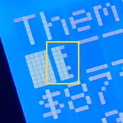
On the host side, providing this data is largely boring and involves getting localised string data, truncating it to fit the requisite number of characters and writing it into a buffer of bytes.
The buffer's first byte is the numeric ID for this report (so the device knows which report it's currently receiving), the second byte contains the length of data inside the report (a length of 0 indicates we want to simply clear the display instead), and the remaining bytes are the actual data to display on the screen, which is just raw ASCII for the most part, with some special values indicating an elipsis (if a string had to be truncated) and the custom symbol for pips on the cut level meter:
// < previous code writing other text into the buffer>

var MassBytes = Encoding.ASCII.GetBytes(CurrentObjectInfo.MassString);
Buffer.BlockCopy(MassBytes, 0, NewObjectInfo, 2 + 40, Math.Min(20, MassBytes.Length));
// Replace the last character with a custom character index depicting an ellipsis for truncation
if (MassBytes.Length > 20)
{
    NewObjectInfo[2 + 40 + 19] = 0b1;
}

var CutLevelBytes = Encoding.ASCII.GetBytes((TryGetLocalizedTextByID(188) ?? "CUT LVL") + " ");
Buffer.BlockCopy(CutLevelBytes, 0, NewObjectInfo, 2 + 60, Math.Min(15, CutLevelBytes.Length));
// Copy in N custom symbols representing cut level pips
int StartingIndex = 2 + 60 + CutLevelBytes.Length;
for (int i = 0; i < CurrentObjectInfo.CutLevel; i++)
{
    NewObjectInfo[StartingIndex] = 0b11011011;
    StartingIndex++;
}
// Store the final length in the buffer
NewObjectInfo[1] = (byte)(StartingIndex + 1);

bObjectInfoDirty = true;
This buffer is then queued up for transmission to the device as a "USB Feature Report".
Hardspace: Shipbreaker Controller Implementation
Implementation breakdown pt 1: Hardware selection
- Implementation breakdown pt 2: 20x4 LCD implementation
Implementation breakdown pt 3: PTZ joysticks
Implementation breakdown pt 4: Switches and buttons and bar graphs, oh my