Custom Hardspace Controller pt 4: Switches and buttons and bar graphs, oh my
I wanted to be able to display the vital signs of the player in some way in the hardware HUD, so when I came across an older module I had already built containing three bar graphs and a number of switches and buttons I thought it would be perfect for this.
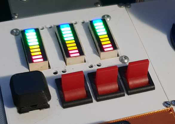
I had originally built this for another project that was long-since mothballed, so being able to use it on something new was definitely attractive.
The problem that I had originally run into while putting together this module was that each LED bargraph was essentially 'dumb' - each LED still required individual control, and that meant using a large number of I/O pins to control them.
The usual solve for this sort of situation might be to try to multiplex the bar graphs - use one set of wires connecting all three bars, then another three wires to turn each graph on, one at a time, at a high frequency. This does drastically decrease the number of pins required - from 30 to 13 - but even 13 I/O pins is an awful lot to use, especially as I was reusing my existing microcontroller design which only had about 25 I/O pins exposed for use, due to my wanting to keep the board size down.
I decided to reduce that I/O pin requirement further, by using an MCP23017 16-pin I2C I/O expander, a much more modern design than the one on the cheap LCDs I used for the object display. The 16 I/O pins that the 23017 had, was enough to handle the multiplexing for the LEDs on its own, and I was already using I2C anyway! I2C allows multiple devices to share the same connection, so I was able to control these LEDs 'for free' from a I/O perspective.
In the context of the original project this module was intended for, I needed an up and down button for each graph and a button to reset things, so I simply added a second MCP23017 to read the state of those switches, configuring it to have a different I2C address so both expanders could be communicated with separately.
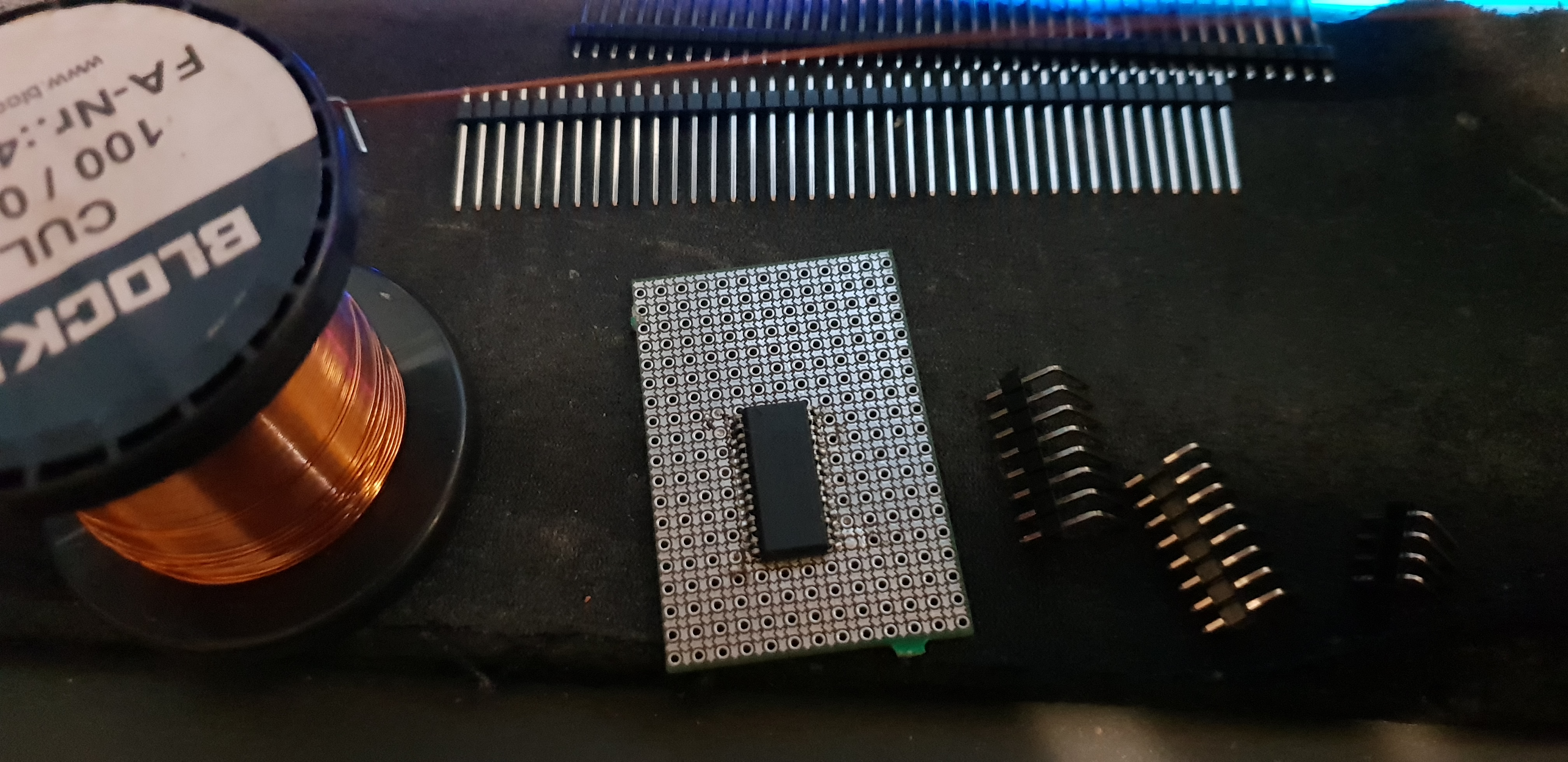
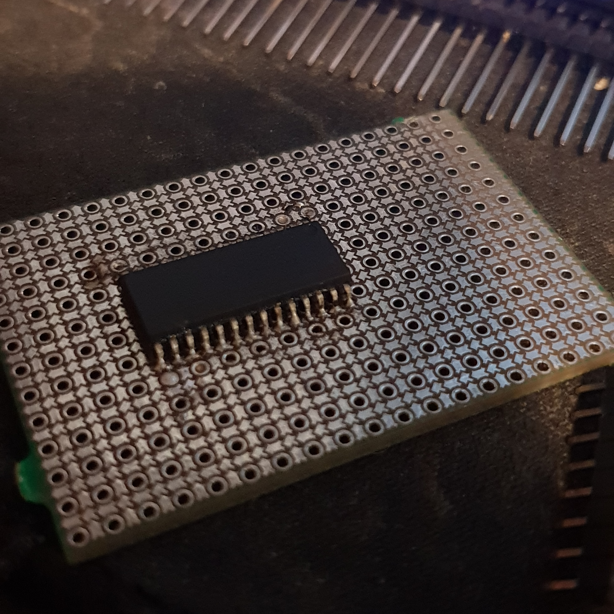
The MCP23017s were soldered down to some prototyping boards, and then all of the LEDs and switches were wired up:
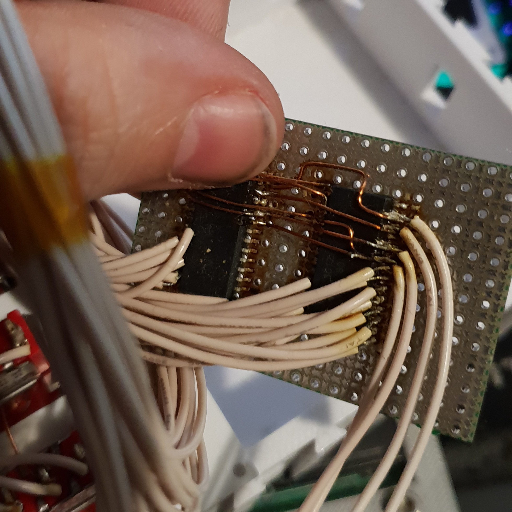
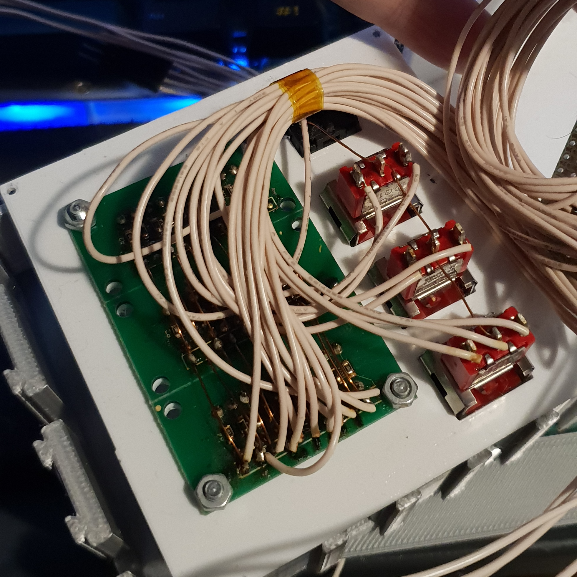
Needless to say, not having to do all that again with so many wires was a strong factor in why I decided to reusing the existing module.
Back on this current project, I knew that while the existing module would be helpful, it wasn't going to provide me with all the inputs that I needed, and I wanted some additional inputs using a different type of switch. For the scanner mode, flashlight and so on, I wanted toggle switches that wouldn't require being held down.
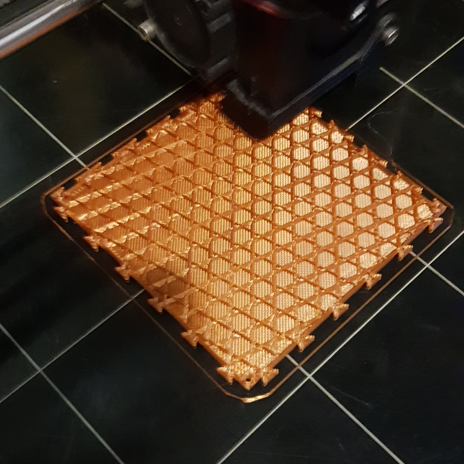
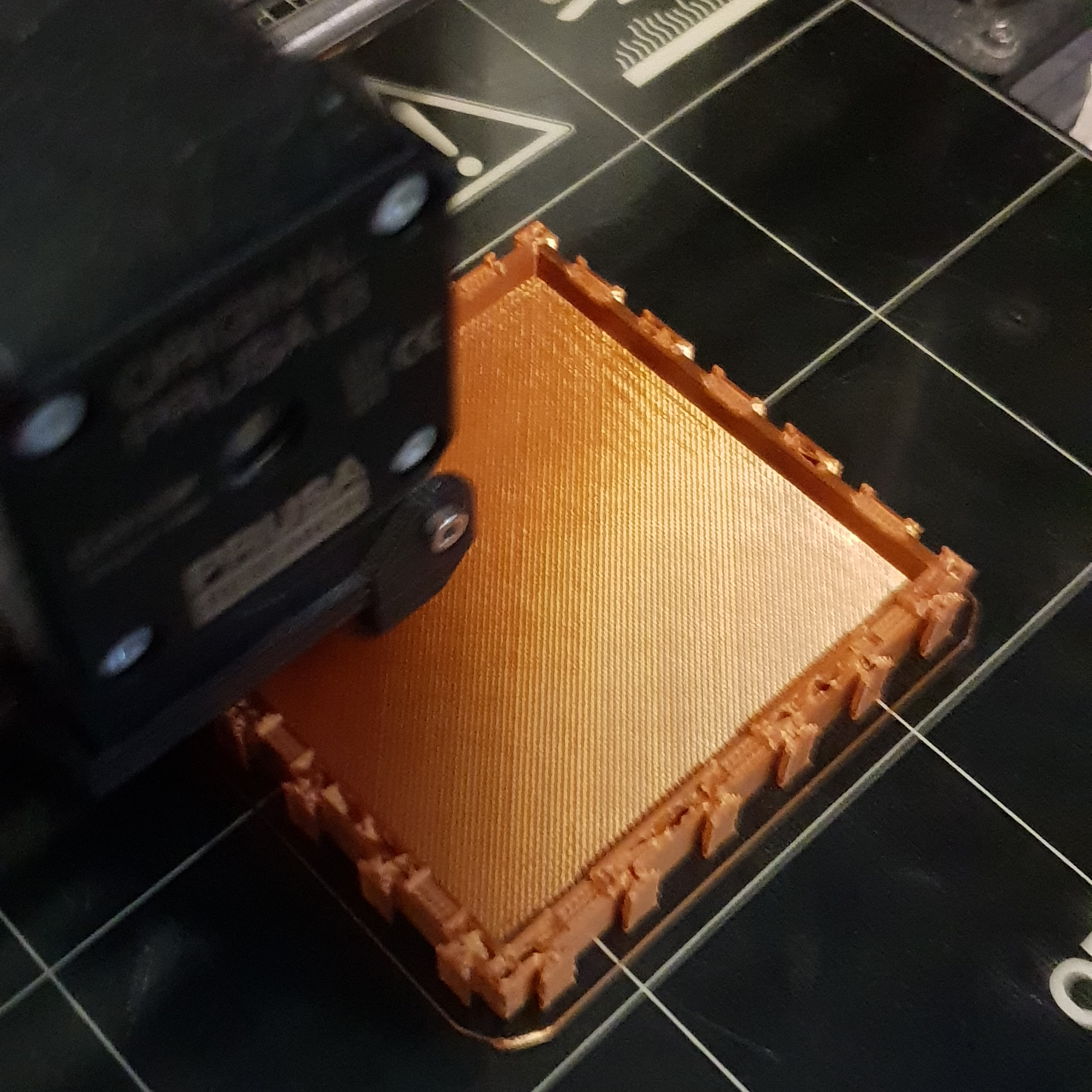
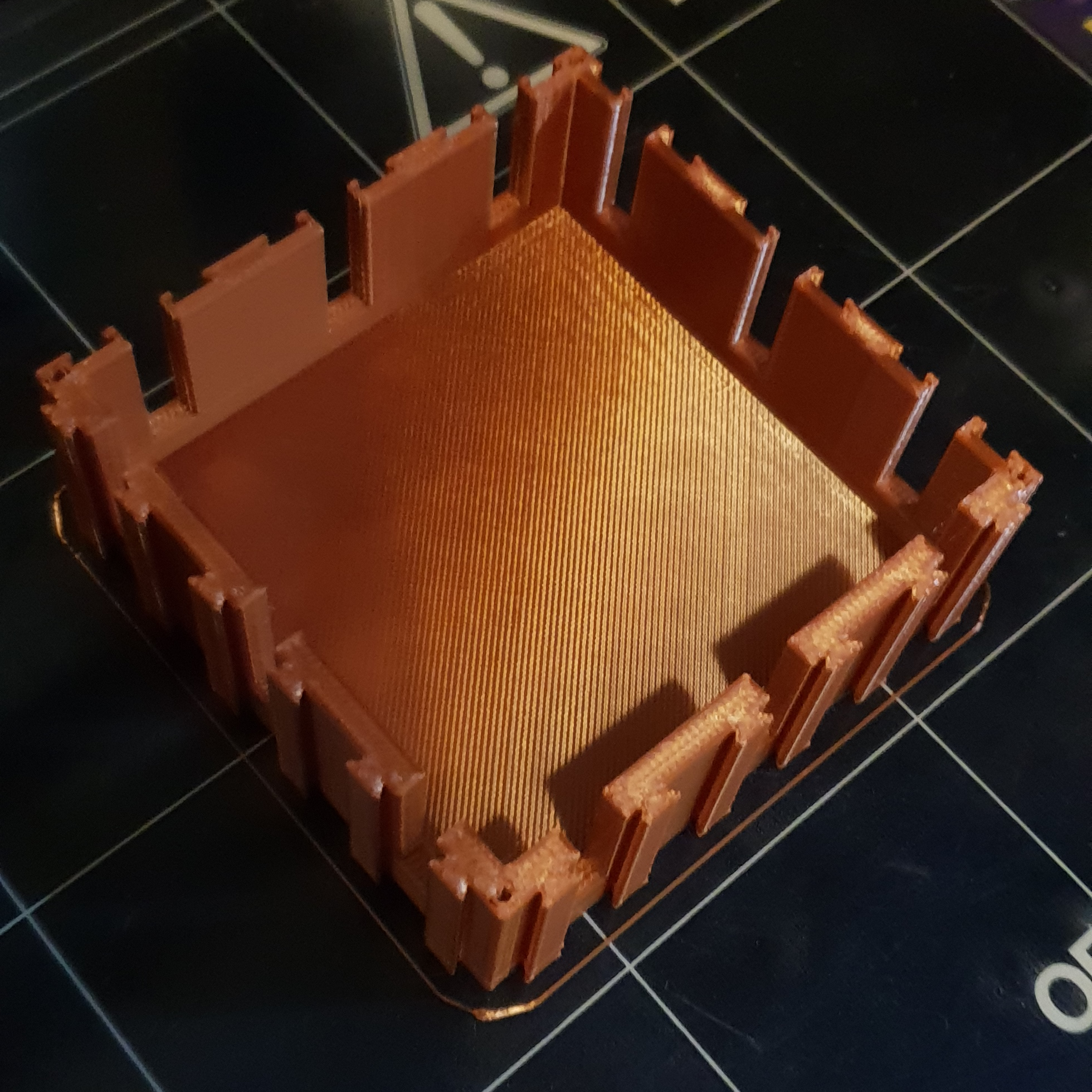
I produced a new enclosure quickly, thanks to my parametric script, and had while that was printing, I moved onto looking at the implementation of the wiring for the new switch panel.
At this time I wasn't completely set on whether to use a TFT screen or not, and because everything other than the joysticks was already using I2C... You guessed it, I just simply grabbed another MCP23017 and wired it up, using enameled copper wire which is particularly nice for creating 'pseudo traces' without having to worry about short circuits.
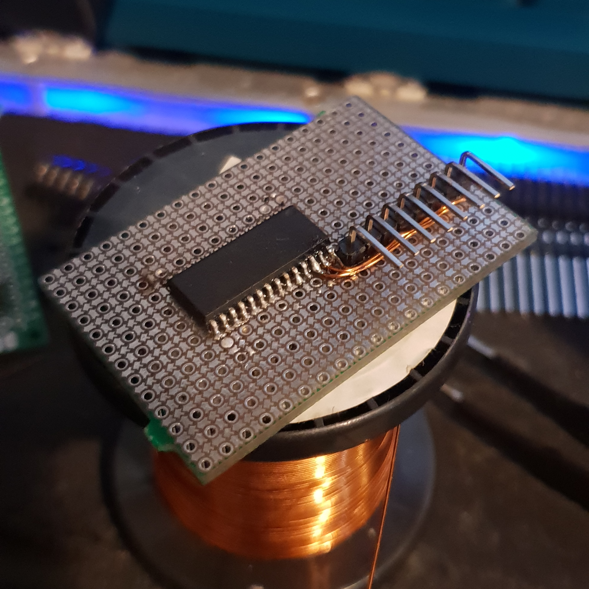
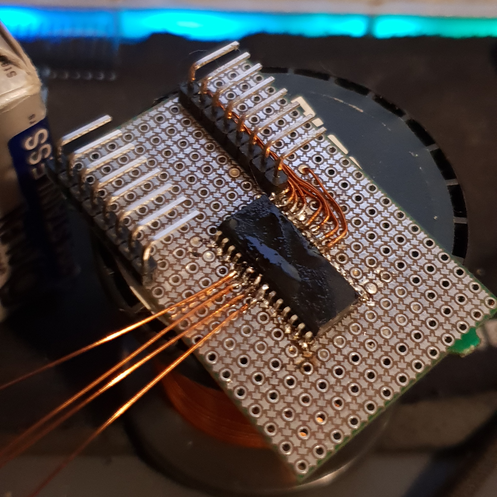

Enameled copper wire is amazing, just saying...
No, really
With the toggle switches and the keyswitches wired up to 'dupont' headers and connected to the little MCP23017 breakout board I'd just created, I was done with the rest of the inputs. Reading the state of all the buttons to include in the input report for the PC was quite easy:
ReportData[15] = I2C<1>::ReadRegister(
			0x25, ToggleSwitches::RegisterAddress(Port::PortA, RegisterType::GPIO));
ReportData[16] = I2C<1>::ReadRegister(
			0x23, ToggleSwitches::RegisterAddress(Port::PortA, RegisterType::GPIO));
ReportData[17] = I2C<1>::ReadRegister(
			0x23, ToggleSwitches::RegisterAddress(Port::PortA, RegisterType::GPIO));
Because the I/O expanders pack the state of their inputs into a byte already, it was trivial to read those values straight into the section of the input report marked up as all the buttons:
Input(MakeButton(10),1,1),
Input(MakeButton(11),1,1),
Input(MakeButton(12),1,1),
Input(MakeButton(13),1,1),
Input(MakeButton(14),1,1),
Input(MakeButton(15),1,1),
Input(MakeButton(16),1,1),
Input(MakeButton(17),1,1),
PaddingItem(ReportType::Input, 4),
Input(MakeButton(18),1,1),
Input(MakeButton(19),1,1),
Input(MakeButton(20),1,1, ReportItemFlags(ReportFlagValues::Relative)),
Input(MakeButton(21),1,1, ReportItemFlags(ReportFlagValues::Relative))
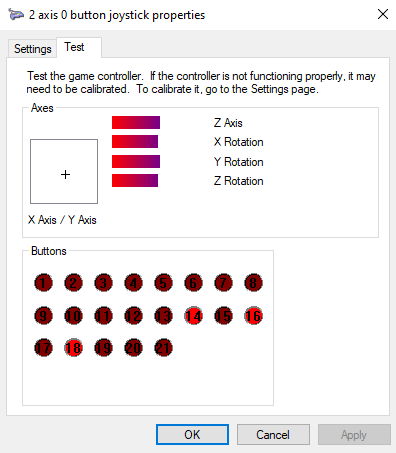
With that done, the device now was detected by Windows with all of the buttons and axes defined:
Hardspace: Shipbreaker Controller Implementation
Implementation breakdown pt 1: Hardware selection
Implementation breakdown pt 2: 20x4 LCD implementation
Implementation breakdown pt 3: PTZ joysticks
- Implementation breakdown pt 4: Switches and buttons and bar graphs, oh my