Custom Hardspace Controller pt 3: PTZ joysticks
As mentioned earlier, one of the central ideas for this project was the use of some off-the-shelf 3-axis PTZ (Pan, Tilt, Zoom) joysticks to provide the analog inputs for the controller. These joysticks have a third analog axis which is controlled by vertically twisting the stick clockwise and counter-clockwise.
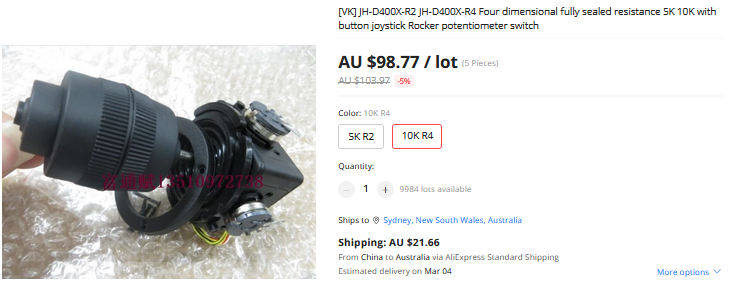
These are overall the simplest part of this project to integrate aside from one minor factor when implementing the device-side code that interprets their signals.
Joysticks and thumbsticks of any sort are usually just a linked set of variable resistors and springs. This means you can connect the two outer terminals to ground and power, and read a voltage from the third central terminal to determine the position of that axis based on it's value as a proportion of the overall input range. In other words, if I connect one outer terminal to 3.3v and the other to ground, I expect a value of approximately 1.65v when that axis is at rest in the middle, if I measure the voltage on the central terminal.
The only difference between these new PTZ joysticks and what you'd expect to see in, say, an XBox controller, is the addition of the third analog axis that requires measurement.
With that in mind, the actual wiring for the joysticks was very simple:
- All three axes have their power terminals linked in parallel
- All three axes have their ground terminals linked in parallel
- The thumb switch has one wire connected to power
- The second wire from the thumb switch and the three axes' middle terminals are connected to I/O pins on the microcontroller
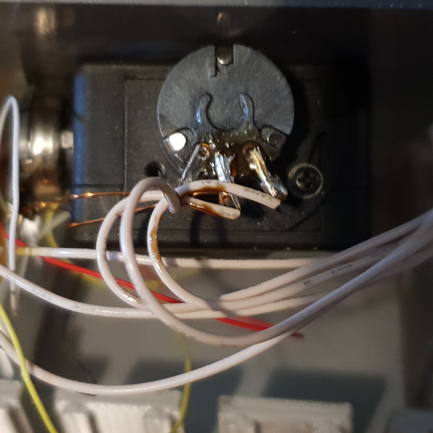
Every hardware engineer looking at this is currently yelling at me about strain relief, I'm sure.
Once all the wiring was done for positive and negative rails plus the four output signals, I needed to use the microcontroller's analog-to-digital converter to actually get the voltage measurements so I could transmit them to the PC.
The STM ADC has a nice feature where you can ask for it to convert a series of analog signals in a single operation, a so-called 'sweep'. The problem with this, is because there's only a single register storing the results of conversion, each new result overwrites the previous one, and of course I really didn't want to just sit there in a loop waiting for each conversion to complete and copy the value before the next one overwrote it. The way around this was to use a system called DMA to automatically copy each conversion result into an array without requiring manual intervention. This involves configuring the ADC to make DMA requests each time a conversion is complete, and then configure the DMA controller to know that when it receives an ADC request it needs to store the results in a specific location.
// Template method that configures continuous DMA from the ADC channels provided and stores the results in a contiguous block starting at Destination
template<std::uint8_t... ChannelIndex>
static void EnableDMAContinuous(std::uintptr_t Destination)
{
    // Enable each ADC channel specified by the user
    (EnableChannel<ChannelIndex>(),...);
    // By default the STM32 ADC gives 12-bit results, so we want to make 16-bit transfers from the DR (data register), one for each channel, and we want to restart the process when we get to the last index.
    DMAConfig CommonConfig =
        DMAConfig()
            .Source<typename ADC::DR>(DMAConfig::AddressType::Peripheral,
                DMAConfig::AddressSize::HalfWord)
            .Destination(DMAConfig::AddressType::Memory, DMAConfig::AddressSize::HalfWord,
                Destination)
            .SetCircularMode(true)
            .DataQuantity(sizeof...(ChannelIndex))
            .AutoIncrementSource(false)
            .AutoIncrementDestination(true);
    DMA::Configure<Config::DMA::ADC, 1>(CommonConfig);
    //With the DMA configured, configure the ADC to make continuous DMA requests and to overwrite old results in case of an overflow
    ADC::CFGR1::template merge_write<typename ADC::CFGR1::CONT,
                                            ADC::CFGR1::CONT_Values::Continuous>()
        .template with<typename ADC::CFGR1::DMACFG, ADC::CFGR1::DMACFG_Values::Circular>()
        .template with<typename ADC::CFGR1::DMAEN, ADC::CFGR1::DMAEN_Values::Enabled>()
        .done();
    ADC::CFGR1::OVRMOD::set();
}


static std::array<uint16_t, 6> AnalogData = {};

//Calibrate the ADC
Joysticks::Calibrate();
// Enable DMA for the specified channels - one for each axis on our two joysticks - storing results
// into AnalogData
Joysticks::EnableDMAContinuous<0, 1, 2, 4, 5, 6>(reinterpret_cast<uintptr_t>(AnalogData.begin()));

Joysticks::Enable();
Joysticks::Start();
In the main loop, I stuffed the results of conversion into a buffer and sent that off to the PC as an Input Report.
The relevant part of the USB HID Descriptor was:
PhysicalCollection
(
    GenericDesktop::Thumbstick(),
    PaddingItem(ReportType::Input, 4),
    Input(GenericDesktop::X(), 1, 12),
    PaddingItem(ReportType::Input, 4),
    Input(GenericDesktop::Y(), 1, 12),
    PaddingItem(ReportType::Input, 4),
    Input(GenericDesktop::Z(), 1, 12),

    Input(MakeButton(1), 1, 1),
    PaddingItem(ReportType::Input, 7)
),
PhysicalCollection
(
    GenericDesktop::Thumbstick(),
    PaddingItem(ReportType::Input, 4),
    Input(GenericDesktop::Rx(), 1, 12),
    PaddingItem(ReportType::Input, 4),
    Input(GenericDesktop::Ry(), 1, 12),
    PaddingItem(ReportType::Input, 4),
    Input(GenericDesktop::Rz(), 1, 12),

    Input(MakeButton(2), 1, 1),
    PaddingItem(ReportType::Input, 7)
),
This section of the descriptor indicates the data is two thumbsticks, each with 4 bits of padding and 12 bits of data mapped to each axis, followed by a single bit indicating the state of the thumb button.
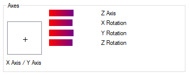
A quick check of joy.cpl in windows showed that the OS was correctly interpreting the descriptor and the input report, and that meant the joysticks were complete.
Hardspace: Shipbreaker Controller Implementation
Implementation breakdown pt 1: Hardware selection
Implementation breakdown pt 2: 20x4 LCD implementation
- Implementation breakdown pt 3: PTZ joysticks
Implementation breakdown pt 4: Switches and buttons and bar graphs, oh my