Custom Hardspace Controller pt 6: BRAAAAINS
This project spent a very significant amount of development time hooked up to the microcontroller - the 'brains' of the project - via a good quality breadboard.
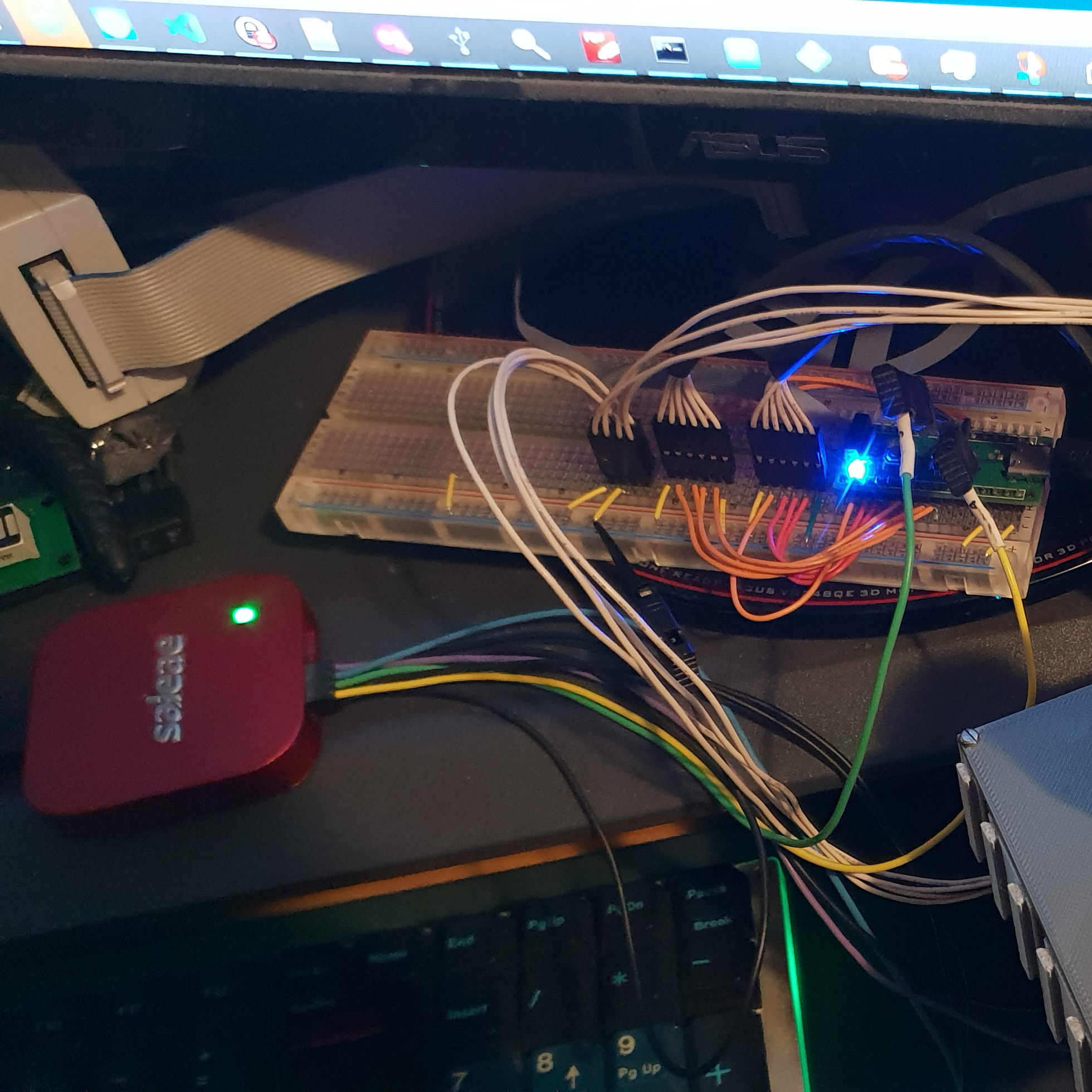
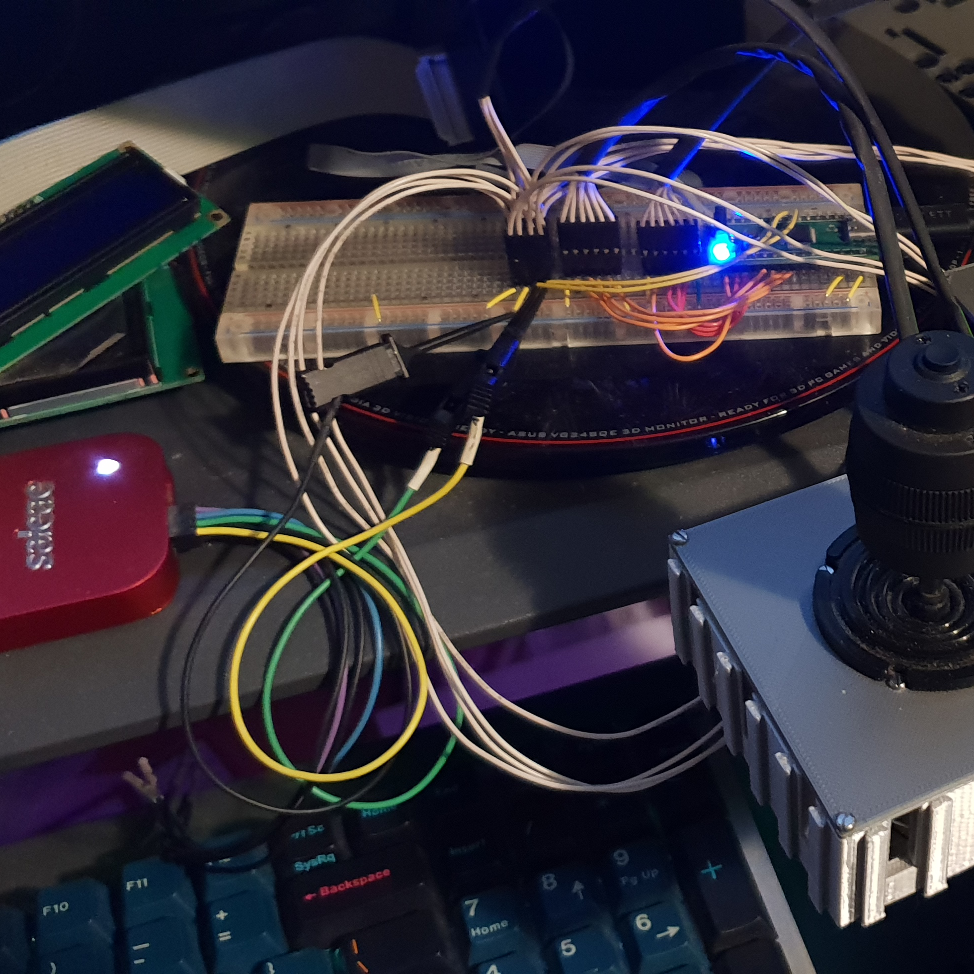
Even after I ran out of room on the breadboard for the number of attached devices on the I2C bus I continued to use one (and a second microcontroller on another devboard) for the initial testing and R+D of the remaining peripheral drivers. They make attaching logic analyzers and other probes much easier, as adding a bare header to the same rows on the breadboard exposes data lines for easy access with standard-pitch grabbers.
However, as I mentioned, I did eventually run out of room for the number of I2C devices I had connected, and I knew that I wanted to make something a little more sturdy, even if I kept the actual microcontroller board detachable from the base board where everything else was connected.
Spinning up a PCB and having it delivered from China is always an option, but I always worry about e-waste when I end up with 10x of a board I might only ever use once or twice. As an alternative, I often use enameled copper wire, and these solderable 'protoboards':
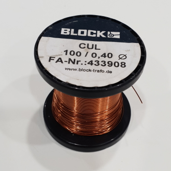
Enameled copper wire has a coating on it - this CUL wire is coated in polyurethane - and if sufficient heat is applied, the coating burns off allowing the bare metal to be exposed. This makes the wire particularly good for applications where you don't want to have to strip and tin every wire, especially ones where a single conductor is acceptable, so long as there isnt excessive vibration that could abrade the coating and allow a short circuit. It's available in a number of different sizes, but I find this 0.4mm wire strikes a good balance between being stiff enough to retain shape well, but not so stiff that it requires pliers to bend.
The easiest way to strip the very tip of the wire is to collect some solder on the tip of an iron, flux the tip of the wire (I use a Chip-quik tack flux in a syringe) then hold it inside the solder blob for 15 seconds or so. If your temperature is hot enough, the insulation should boil off and you'll be left with a very small tinned area of wire at the end. This is then easily soldered to header pins, plated through-holes or anything else, as it is effectively bare wire.
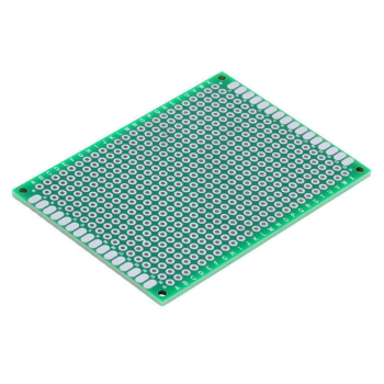
The green 5x7cm double-sided protoboards are generally speaking well made. Their plated-through-holes seem to detach significantly less often than the single-sided brown boards of the same size. They are available cheaply through Aliexpress.
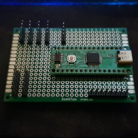
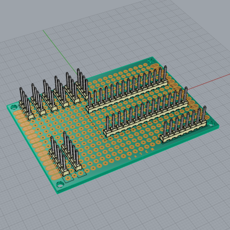
The first thing I did was double-check that the number of through-holes in a 5x7 board would be sufficient for all the devices that I wanted to connect. This basically just involved me breaking some 0.1" header pins off into groups representing each connection I wanted to make, and doing a test placement into the protoboard along with the controller itself.
No soldering required, just making sure that there wasnt any strange overlaps or spots where a connector would be too close to the board to be plugged in, those sort of issues.
With that done, I was able to begin to solder the actual connectors on. The first thing I did was solder the 'socket' for the actual development board, which was in actually just two rows of female header pins soldered in at the correct spacing. I then added all six sets of header pins for the I2C bus, as I knew that all those devices would effectively be wired in parallel and it would make sense to use a single wire for each set of parallel connections.
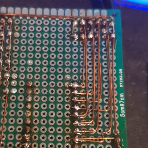
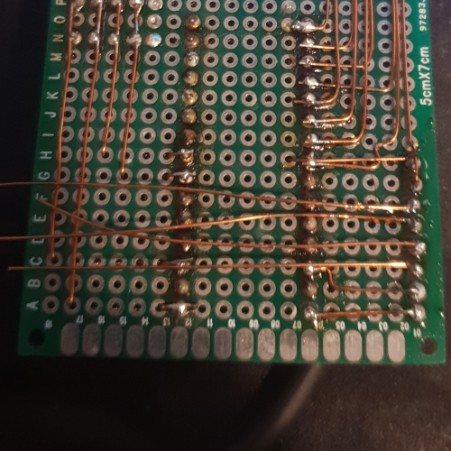
One thing I often like to do when wiring devices up on these protoboards is use the intervening through-holes to make things right-angled and neater, which can be seen in this image, taken after I had wired up the I2C bus. After soldering the wires to the socket for the board, I threaded the wire through the board to the other side, and then back, through the hole which is aligned with the set of pins I want to connect it to. In addition to making a neat right-angle, this helps to secure the wires so they dont move about.
Following on from the wiring of the I2C connectors, I then integrated the analog inputs. The analog connections were a little more tricky, as they weren't connected, so I soldered the inner set of connections first, and then the outer ones over the top:
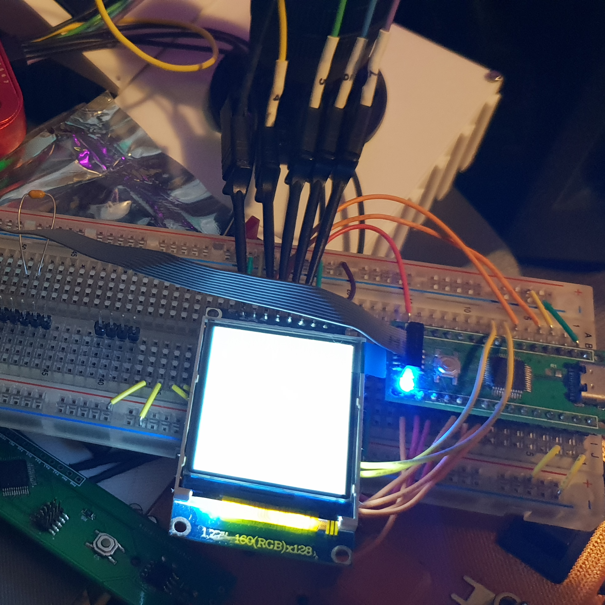
With the analog section complete, the last remaining group of connections was for the TFT screen:
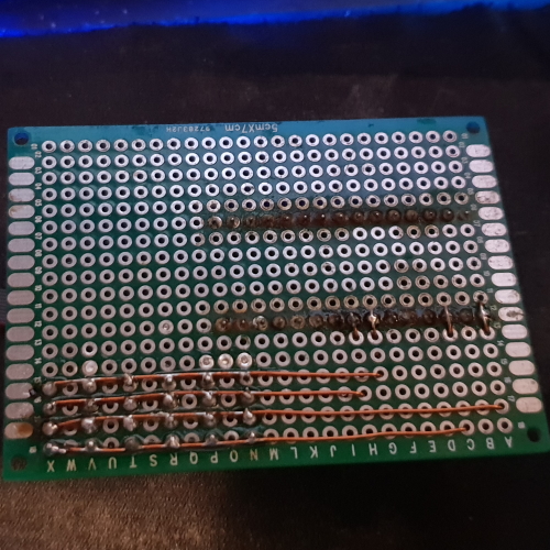
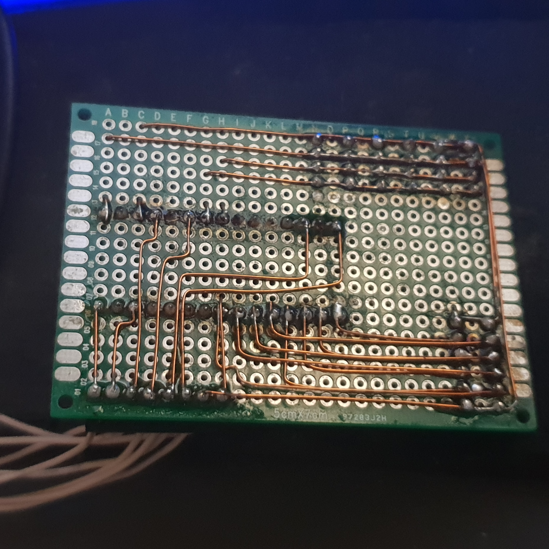
This image demonstrates my overall approach when using enameled copper wire. Cut a number of lengths of wire slightly longer than necessary, tin their ends as mentioned before, and then one by one solder them to the existing pins in the protoboard. Once anchored at one end, the wires can be bent or threaded through the board as necessary until they come into contact with the other pin they should be soldered to. The wire can then be trimmed to that length, and that end also tinned as before. Once bare metal is exposed the wire can be placed against the pin, the joint heated, and the wire pushed in to make contact. The offcuts from this process can be used for other connections that are short in length. After each point-to-point connection is complete, they are verified using a multimeter before moving onto the next connection.
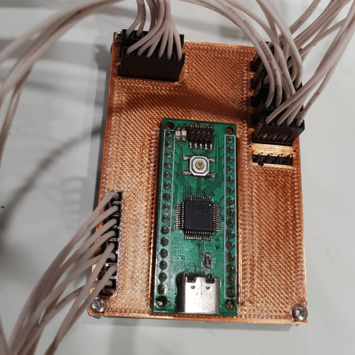
With all of the point-to-point wiring between the pin headers and the development board socket complete, the board itself was now complete:
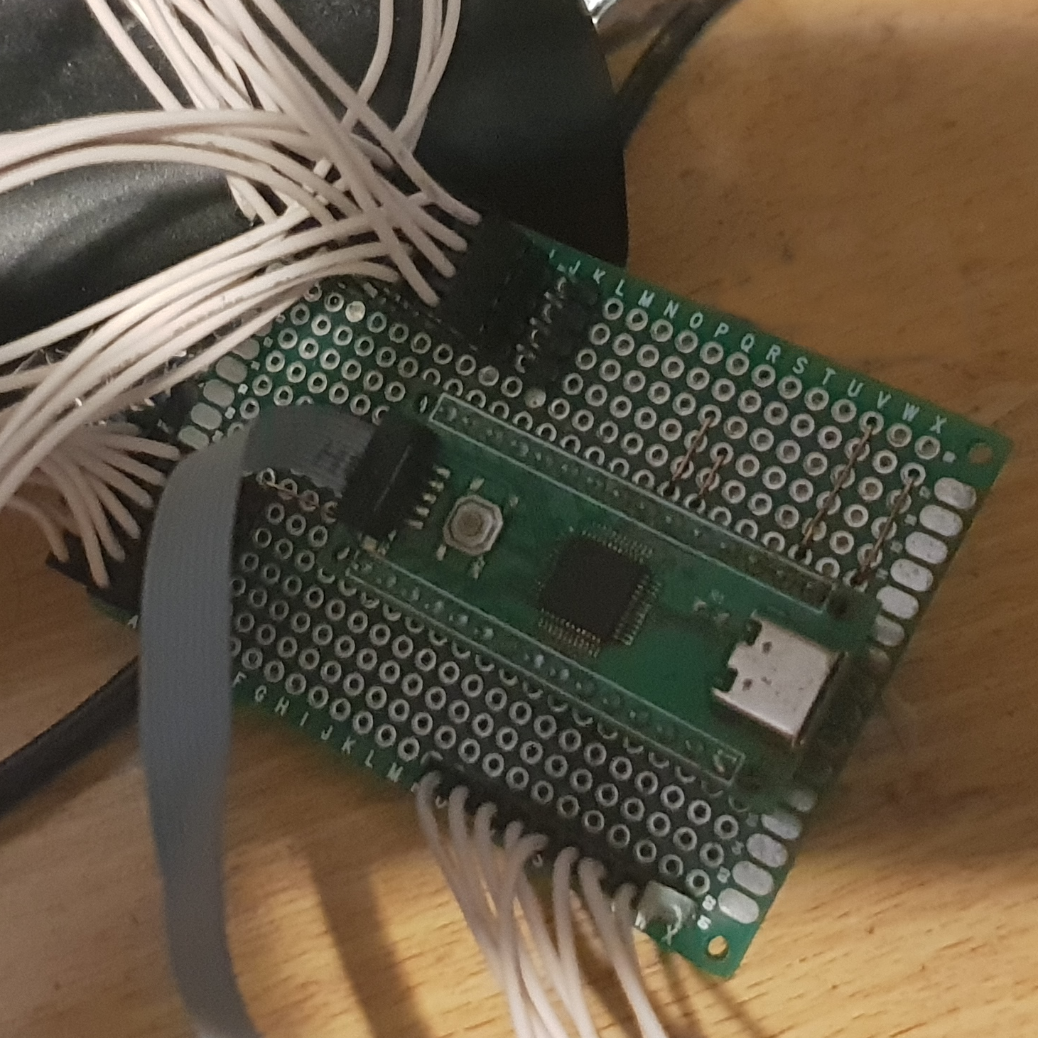
why yes, I do use tack flux liberally. However could you tell?
One thing that I did notice while testing the finished board, however, was that 2.54mm/0.1" headers aren't exactly known for their tight tolerances, especially when you buy your headers and sockets from Aliexpress ;)
There was a bit of free play in the female connectors that I hand-crimped onto the wires, and so I decided that the best way to keep them from moving too much was to print a plate that could be screwed down to the mounting holes on the PCB to stop the plug housings from wiggling.
I quickly mocked up the PCB in Rhino, and then used that to place cutouts in a rectangular plate.
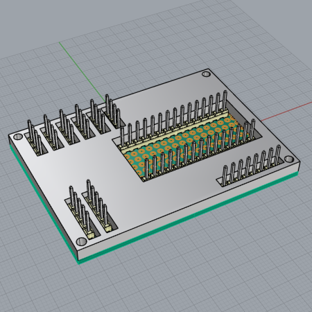
One quick 3D print later, and I had a plate to install onto the board:
With that in place, the project was complete.
You can see the final result in action here
Hardspace: Shipbreaker Controller Implementation
Implementation breakdown pt 1: Hardware selection
Implementation breakdown pt 2: 20x4 LCD implementation
Implementation breakdown pt 3: PTZ joysticks
Implementation breakdown pt 4: Switches and buttons and bar graphs, oh my
Implementation breakdown pt 5: Of TFTs, and scope creep
- Implementation breakdown pt 6: BRAAAAINS